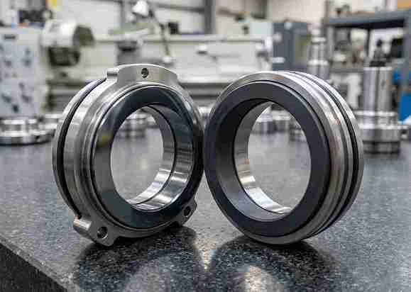
Turbine Carbon Seal Rings for Shaft and Gland Sealing
CARBOLVE manufactures segmented carbon rings, mechanical seal faces, floating-ring components and custom replacements for turbine sealing applications. Components are evaluated from drawings, physical samples, equipment information and operating conditions.
- Segmented and single-piece carbon ring configurations
- Custom floating-ring and replacement components
- Carbon graphite and application-reviewed impregnated grades
- Drawing-based machining and inspection

Turbine Carbon Seal Ring Configurations
Begin with the ring construction and its position in the turbine sealing arrangement. Material selection follows after the shaft, gland, clearance, pressure and temperature conditions are understood.
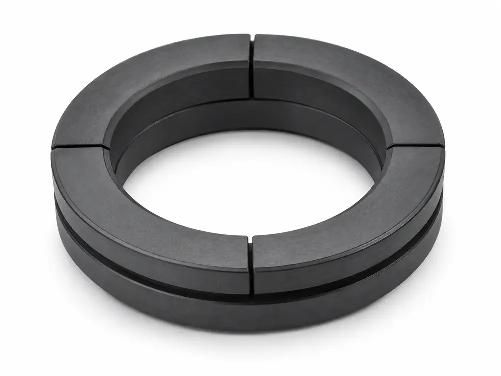
Segmented Turbine Carbon Seal Rings
Multi-segment carbon graphite rings for selected turbine shaft and gland-sealing arrangements. Segment geometry, joint form, running clearance and material direction are reviewed with the shaft and operating conditions.
Select by shaft diameter, segment arrangement, joints, clearance, steam or gas conditions.

Turbine Carbon Mechanical Seal Rings & Faces
Single-piece carbon graphite rings and flat or profiled seal faces manufactured to the supplied drawing, dimensions, mating-face information and surface requirements.
Select by seal-face geometry, mating material, pressure, speed and required surface condition.

Floating Carbon Seal Rings for Turbines
Custom floating carbon ring components manufactured from drawings or samples for seal arrangements that permit controlled movement or close-clearance operation. The housing, shaft or sleeve and complete sealing system must be evaluated separately.
Select by housing geometry, shaft or sleeve size, clearance, pressure zones and movement.
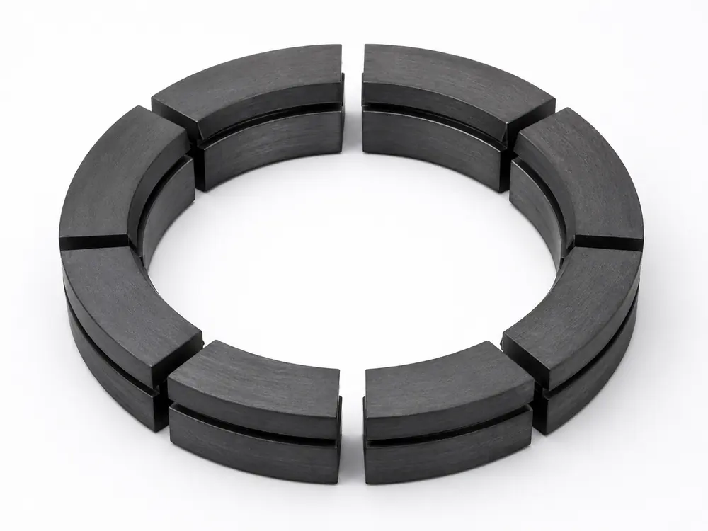
Custom & Replacement Turbine Carbon Components
Carbon rings, seal faces and non-standard components produced from drawings, physical samples or equipment information. This route supports maintenance parts, obsolete replacements, repeat orders and new component designs.
Start with an identifiable drawing, measured sample, turbine model or existing component information.

How Turbine Carbon Rings Control Steam or Gas Leakage
A turbine carbon seal ring surrounds or works against a rotating shaft, sleeve or mating face to restrict the movement of steam, gas or oil between pressure zones. The exact sealing action depends on the ring and gland design.
In a typical segmented gland arrangement, several carbon rings may be installed in sequence. Each ring creates a controlled restriction, allowing the pressure to decrease across the sealing stages. The ring may also form a face seal against a gland wall or separator surface.
Important Control Principle
Carbon rings control leakage; they do not create an absolute zero-leakage barrier. Running clearance, segment joints, pressure differential, thermal expansion, shaft condition, alignment and the complete gland arrangement determine the result.
CARBOLVE supplies carbon seal rings and related components. The turbine manufacturer, seal-system designer or qualified maintenance team remains responsible for validating the complete assembly.
Choose the Ring Construction Before the Material Grade
| Configuration | Practical difference | Typical starting situation | Key selection information |
|---|---|---|---|
| Segmented turbine carbon ring | Multiple segments assembled around a shaft or sleeve | Turbine gland or shaft-sealing position requiring split installation or controlled clearance | Shaft diameter, segment count, joint form, gaps, clearance, pressure and temperature |
| Mechanical seal ring or face | Continuous ring with a flat or profiled sealing face | Turbine-related mechanical seal assembly requiring a carbon face | Drawing, dimensions, mating face, surface requirements, pressure and speed |
| Floating carbon ring | Carbon ring permitted to move within a defined housing arrangement | Custom close-clearance or floating-ring seal design | Housing drawing, shaft or sleeve condition, radial clearance and pressure zones |
| Custom replacement component | Existing component reproduced or revised from technical evidence | Maintenance, obsolete part or equipment without a current standard component | Drawing, sample, photographs, turbine model, measured dimensions and operating conditions |
Similar dimensions do not make two turbine carbon rings interchangeable. Confirm the component function, segment and joint arrangement, operating clearance, mating parts and material before ordering a replacement.
Carbon and Graphite Material Options
CARBOLVE’s engineering grade system covers resin-impregnated carbon graphite, antimony-impregnated carbon graphite, copper-impregnated carbon graphite, unimpregnated carbon, fine-grain carbon, electrographite and selected application-specific treatments.
For turbine applications, the grade must be evaluated with the steam or gas, atmosphere, pressure differential, shaft speed, thermal cycle, ring construction, running clearance, mating surfaces and required leakage control.

| Material family | CARBOLVE grades | Preliminary material direction |
|---|---|---|
| Unimpregnated Carbon Graphite | CVM-CG-U10 | Segmented-ring and selected porous-service directions |
| Resin-Impregnated Carbon Graphite | CVM-CG-R20, CVM-CG-R30, CVM-CG-HR40 | General mechanical seal, higher-load resin and elevated-temperature resin directions |
| Antimony-Impregnated Carbon Graphite | CVM-CG-A20, CVM-CG-A30, CVM-CG-A40 | Steam, light hydrocarbon, high-load and severe-duty seal directions |
| Copper-Impregnated Carbon Graphite | CVM-CG-C30, CVM-CG-C40 | Applications requiring a higher-pressure or heat-removal material direction |
| Electrographite | CVM-EG-U20, CVM-EG-R20 | Elevated-temperature and selected dry-running ring directions |
| Fine-Grain Carbon Graphite | CVM-FG-R30, CVM-FG-A40 | Precision seal-face and severe-duty material directions |
| Application-Specific Grades | CVM-CG-Y30, CVM-CG-PT20, CVM-CG-NC40 and other reviewed grades | Chemical-duty or special operating conditions requiring individual evaluation |
These grade directions support preliminary material selection. They are not guaranteed specification limits, universal turbine pressure ratings or service-life values. Final suitability depends on the actual ring geometry, fit, atmosphere, shaft condition, PV conditions, cooling and operating medium.
Match the Carbon Ring to the Turbine Conditions
| Operating or design condition | Initial direction to review | Additional validation required |
|---|---|---|
| Segmented steam-gland ring | Unimpregnated carbon or an application-reviewed impregnated grade | Steam quality, pressure differential, shaft speed, clearance, joints and condensate exposure |
| Higher mechanical load or steam service | Antimony-impregnated carbon graphite | Actual temperature, atmosphere, shaft condition, fit and complete gland design |
| Elevated-temperature or selected dry-running service | Electrographite or an elevated-temperature resin direction | Oxidizing or non-oxidizing atmosphere, thermal cycling, speed and running clearance |
| Precision mechanical seal face | Fine-grain resin- or antimony-treated carbon | Mating-face material, flatness, surface requirements, loading, speed and cooling |
| Higher pressure with heat-removal requirements | Copper-impregnated carbon graphite | Thermal conditions, medium compatibility, geometry and system-level validation |
| Chemically demanding gas or medium | Redensified, PTFE-treated or another reviewed grade | Chemical compatibility, atmosphere, gas tightness and leakage requirements |
| Existing turbine replacement | Match the verified material family and component construction | Original drawing or sample, wear pattern, shaft condition, dimensions and operating history |
A material grade alone does not determine maximum pressure, leakage or service life. Ring geometry, clearances, fit, mating parts and the turbine operating cycle must be considered together.
Common Turbine Carbon Ring Failure Modes
Increased leakage or abnormal wear does not automatically mean that the carbon material is defective. Inspect the ring, shaft, gland and operating history as one system.
Bore or sealing-surface wear
Gradual wear can increase the effective clearance and allow more steam or gas to pass. Review the wear pattern together with shaft condition, alignment, speed and contamination.
Chipped or broken segments
Impact during handling, incorrect assembly, thermal shock, insufficient clearance or contact with a damaged shaft may contribute to edge damage or segment breakage.
Uneven wear
Misalignment, shaft runout, housing distortion, incorrect loading or an uneven mating surface can concentrate contact on part of the ring.
Sticking or restricted movement
Deposits, corrosion products, oil contamination or incorrect fit may prevent segmented or floating components from moving as intended.
Thermal or material mismatch
An unsuitable impregnation, atmosphere or thermal cycle may change the material response. Temperature capability must be considered together with oxidation conditions and ring geometry.
Incorrect replacement geometry
A visually similar ring with different joints, gaps, grooves or clearances can change the sealing behavior even when its main diameters appear correct.
Reduce Avoidable Replacement Mismatches
Ordering by turbine model alone
A turbine model may use different gland or seal arrangements. Confirm the ring position, construction and available part reference before selecting a replacement.
Measuring only the main diameters
Segment joints, side width, face geometry, grooves, locating features, gaps and assembly orientation may be equally important.
Replacing the ring without checking the shaft
A worn, scored or misaligned shaft or sleeve may affect the behavior of the replacement component. Record the mating-surface condition during inspection.
Selecting from a competitor grade name
CARBOLVE grade numbers do not represent automatic equivalence to another manufacturer’s material. Compare the base carbon family, impregnation, operating conditions and required properties.
Defining inspection requirements after production
Critical dimensions, surface condition, identification and packing requirements should be agreed before manufacturing begins.

From Turbine Information to Finished Carbon Components
CARBOLVE coordinates material direction, ring geometry, machining requirements and inspection information within one component review. Production can be evaluated from a technical drawing, physical sample, turbine information, photographs and operating conditions.
Identify the component
Confirm the turbine or seal reference, ring position, function and available technical information.
Define geometry and material direction
Review dimensions, segments, joints, gaps, clearances, mating surfaces, carbon family and surface requirements.
Machine and finish the ring
Apply grinding, drilling, slotting and surface-finishing operations according to the agreed component geometry.
Inspect and prepare the order
Check agreed dimensions, surface condition, quantity, identification and protective packing before dispatch.
This approach supports new components, maintenance parts, obsolete replacements and repeat-order requirements without assuming that visually similar turbine rings are interchangeable.
Manufacturing and Inspection for Carbon Seal Components
CARBOLVE manufactures industrial carbon and graphite components for equipment manufacturers, distributors and maintenance companies. Turbine seal ring projects are reviewed against the agreed component and application information.
- Incoming material review
- In-process dimensional checks
- Surface, edge and joint inspection
- Final verification against agreed requirements
- Product identification and protective packing
- Technical communication and export documentation
For replacement and repeat-order parts, keep the approved drawing or sample reference connected to the material direction, inspection requirements and product identification.


Turbine Carbon Seal Ring Selection and Maintenance Guide
What are carbon seal rings used for in turbines?
Carbon seal rings are used to restrict steam, gas or oil movement along a rotating shaft or between pressure zones. In segmented gland arrangements, several rings may provide successive pressure restrictions while maintaining a controlled running clearance around the shaft.
Other turbine designs may use a carbon ring as a mechanical seal face or floating sealing component. The ring function must therefore be identified before selecting a replacement.
How do turbine carbon seals prevent leakage?
They control leakage through the relationship between ring geometry, segment joints, running clearance, pressure differential and the surrounding gland or housing. In staged arrangements, each ring reduces part of the pressure rather than creating one absolute barrier.
Wear, shaft movement, thermal expansion and deposits can change the effective clearance. Carbon rings should be described as leakage-control components, not zero-leakage seals.
How should the right turbine carbon seal ring be selected?
First identify the ring position and construction: segmented gland ring, mechanical seal face, floating ring or custom replacement. Then compare the steam or gas, pressure differential, shaft diameter and speed, temperature, atmosphere, thermal cycle, running clearance, mating surface and leakage requirement.
The material grade should be selected only after these conditions are known.
What should be compared for a gas-turbine carbon ring?
Compare the actual gas composition, operating and transient temperatures, shaft speed, pressure zones, thermal expansion, atmosphere, clearances and ring arrangement. Also verify whether the carbon component is contacting, segmented, floating or part of another seal assembly.
Do not select a gas-turbine component from a generic ‘top-rated’ list or an unexplained maximum-temperature claim.
How often should turbine carbon seals be inspected?
There is no universal inspection interval for every turbine. Follow the equipment manufacturer’s maintenance schedule and adjust condition monitoring to the duty cycle, steam or gas quality, leakage trend, shaft condition, vibration history and previous wear pattern.
Useful inspection opportunities include planned outages and any event involving increased leakage, abnormal temperature, vibration, noise, oil contamination or a change in operating conditions.
What should be recorded during inspection?
Record ring identification, segment condition, bore or face wear, chips or cracks, joint and gap condition, deposits, housing movement, shaft or sleeve surface condition, runout information when available and the observed leakage behavior.
Photographs and dimensional records make a replacement review more useful than a product name alone.
What are the basic steps for replacing a turbine carbon seal ring?
Turbine inspection and replacement must be performed by qualified personnel under the equipment manufacturer’s procedures. Isolate, depressurize, cool and lock out the equipment before opening the gland or seal area.
Record the original ring sequence and orientation, remove components without damaging reference surfaces, inspect the shaft and housing, compare the replacement dimensions and material, and reinstall according to the specified joints, gaps, clearances and loading arrangement. Do not invent torque values or clearances when the original documentation is unavailable.
How should turbine carbon seal ring suppliers be compared?
Compare the supplier’s product scope, material-grade information, ability to distinguish segmented, mechanical and floating components, drawing or sample review, machining processes, inspection checkpoints, identification and packing practices.
A supplier comparison should be based on identifiable technical requirements and documented scope—not unsupported rankings, generic quality language or competitor-grade equivalence.
Inspection and Replacement Safety
Turbines can retain pressure, heat and stored rotational energy. Inspection or replacement of carbon seal rings must follow the turbine manufacturer’s shutdown, isolation, depressurization, cooldown and lockout procedures and must be performed by qualified personnel.
General product guidance does not replace the equipment service manual, approved clearances, installation sequence or site safety procedure.
Discuss Your Turbine Carbon Seal Ring Requirement
Share the available drawing, sample, turbine information and operating conditions. This supports a focused review of the ring construction, material direction and manufacturing requirements.